|
Travel back to a time before atomic clocks,
when you could build a clock in a class with world standards!
By Stephen H. Lafferty
When Quartz Was King
Quartz crystal clocks were the world standard of time before roughly 1955. The first quartz clock was built at Bell Telephone Laboratories in 1927 and in 1929 the U.S. National Bureau of Standards (NBS, now NIST) placed four such oscillators in operation as its primary frequency standard. (at right)
NBS built the first atomic clock in 1949 but due to turmoil at the agency, they were not the first standards organization to put one into service. That honor goes to the National Physical Laboratory in England which built the first successful, atomic, primary standard in 1955. In the United States, NBS finally put its atomic clock into regular service in 1959.
Thus, until then, quartz was the king of time standards, at least in the United States. So in September, 1957, when Scientific American published an article describing how to build your own quartz clock, it was something of a state-of-the-art wonder. The guest author of the article (except for the introduction) was W.W. Withrow, Jr. He’s described only as a radio amateur from Teague, TX. While I’m going to be blunt about pointing out problems with the design, please bear in mind that I’m grateful for his pioneering contribution and have nothing but respect for his efforts.
Science Fair Tale
I was eight years old in 1960 and remember being in awe of my big brother Bill’s electronic projects. It seemed like he was always building Heathkits and tinkering with all kinds of hifi, TV and radio equipment. But his science fair projects were truly remarkable feats of electronics for a high school student. That year, his Stereo Light Beam Transmitter not only won the local and regional fairs but went on to win third place at the national science fair held at Michigan State University.
The 1961 science fair season was coming up in April and what could he do to top that? We had a subscription to Scientific American, which had a regular do-it-yourself feature called “The Amateur Scientist”. I enjoyed reading that section in later years. I don’t know whether Dad suggested the four-year-old article mentioned above or what, but Bill dived into building that complex, vacuum tube project.
This was substantially more difficult than the Stereo Light Beam Transmitter. With its regulated power supply, crystal oscillator, four frequency dividers and high voltage power amplifier, I can attest that it was not easy even now, for this experienced engineer. I still remember being down on the rug of our basement “rec-room” when he was shooting scope photos (left) to illustrate how the multivibrator frequency divider chain worked. There, he set up the finished clock, an oscilloscope and Dad’s ancient folding-bellows camera. It had a huge negative size and Bill used a translucent screen at the film plane to focus closely on the oscilloscope display.
When Dreher High School (Columbia SC) had its Science Fair on April 9, 1961, Bill was there with the clock and an impressive display. It won First Place! He went on to the regional science fair at the University of South Carolina, (two pics at right) where it won an Honorable Mention. While that was certainly an excellent achievement, it must have been a little disappointing, since this was a much more impressive project than the one which had taken first place the year before. When asked about that now, he says that it might have been that the judges didn’t really understand the significance of the recently “state-of-the-art” time and frequency standard. Whereas, the stereo light beam transmitter was easily understood: you just listen, put your hand across the beam and can experience what is going on. Well the clock was still an awesome project! It also made a big impression on me.
Deciding to Build a Reproduction
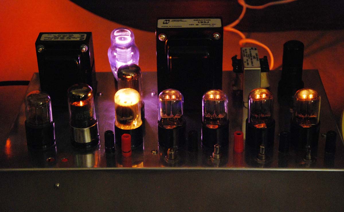
This and Bill’s other projects inspired me to pursue a rewarding career as an electronic design engineer. Sadly, the original quartz clock was lost among his many moves but Bill still had the crystal and the synchronous electric clock which was used with the project. For a long time, I had toyed with the idea of reproducing the project and Bill said that if I did, he would contribute the original crystal and electric clock. It certainly is an intriguing vacuum tube system. The dynamic circuit operation is complex and interesting. While it doesn’t have lots of “blinkenlights,” the tube glow when the room lights are off is entrancing. A cool, lavender glow is emitted from the voltage regulator tube. There is also the slow rise and fall of the phase indicator light, which is surprisingly useful. Lots of adjustments to play with! How could I not build it?
What Can You Change in a Reproduction?
Many years of doing restorations of vintage electronics have taught me to clearly define the boundaries between what should be improved and what should be left original. Generally, my approach has been to leave as much original as possible, while fixing things which are broken. In addition, I usually look to see if there are simple changes I can make which will provide substantial improvements. For a reproduction like this though, the rules needed to be slightly tighter. I settled on building it as close to the original as possible, consistent with safety and proper operation. Also, a few unobtrusive additions were allowed to facilitate maintenance. Other than that, I was prepared to wrestle-down my inner engineer, should he be tempted to redesign stuff.
Overview of the Original Design
As seen in the block diagram at right, this project generates accurate, 60Hz power to drive an ordinary, synchronous-motor, electric clock. Such clocks effectively count cycles to display time and are as accurate as the frequency of the power used to drive them.
The stable, 120kHz crystal oscillator is buffered to prevent disturbances from the divider chain. Each frequency divider block is an astable multivibrator (AMV). That circuit oscillates freely at an adjustable frequency but can synchronize to pulses supplied at a higher frequency. Thus, they can be used to accurately divide frequency. Four stages are used to develop the final 60Hz from the crystal frequency. A driver and power amplifier (PA) boost the level to provide 120Vrms to run the electric clock.
Secrets of the AMV Frequency Divider
How does an AMV work, anyway? So far, we know that it’s an oscillator which has a tendency to synchronize with injected pulses. At left, is a typical AMV circuit, redrawn to emphasize the fact that it is simply two, ordinary, AC-coupled amplifier stages. (The “normal” way of drawing the circuit is below right.) The first is driving the second and the output of the second is connected back to the input of the first. Since each stage inverts the signal, the feedback is positive, so it must oscillate.
In operation, each stage switches between full-on (zero grid bias) and cutoff, spending only an instant in the transitions. The secret to it is this: the timing is always determined by the stage which is cutoff. Right after V1B turns on, the negative-going transition at its plate is coupled by C1 to the grid of V1A, driving it well below cutoff. R1 starts discharging C1, causing the negative voltage at V1-1 to decay towards zero. Nothing much happens until the grid reaches the cutoff voltage. Then V1A turns on, V1B turns off and the roles of the stages are reversed.
So how does it synchronize to an incoming frequency? Let’s go back to the point when V1A is cutoff and its negative grid voltage is rising towards the cutoff threshold. If we apply a positive pulse at the grid, it can be made to trigger earlier than normal. Thus, if we adjust the free-running frequency (Fo) slightly lower than an incoming pulsed signal, the AMV can synchronize to the pulse rate. Notice though, that if Fo drifts above the pulse rate, it will lose sync. Also, if Fo drifts low enough, the negative voltage on the grid may not have risen close enough to cutoff for the pulse to trigger it and it will lose sync that way, as well.
So how does it divide frequency? The input pulse rate can be integer multiples of the AMV’s nominal frequency and it will still synchronize. So for example, if the AMV is tuned just below 1kHz and the input pulse rate is 3kHz, it will synchronize and the output frequency will be exactly 1kHz. However, as the ratio gets higher (say above ten or so) the chances increase that drift will cause it to lock onto a nearby, wrong multiple. Even with such limited divide ratios though, it is still far more efficient than digital flip-flops in terms of the number of tubes required. This project uses 8 amplifying stages to divide by 2000. A digital divider would need 11 flip-flops, which is 22 amplifying stages.
Is it Digital?
Some analog devotees might feel queasy around digital circuits, so the question arises: is the AMV digital? It’s true that it has two quasi-stable states (which look suspiciously like binary to queasy types) but the timing is what matters. That’s determined by the RC components going into the tube that is cutoff at the moment. During it’s cutoff period, the tube’s grid is negative and discharging towards zero. The half-cycle ends when the grid voltage reaches the tube’s cutoff voltage. Thus, the timing and principal function of the circuit is based on analog quantities, making it an analog circuit. No antacid needed.
Original Circuit
We have the original quartz clock schematic at right (click for a larger image). Saving a detailed description for the final circuit, we’ll just make some general comments here. The crystal oscillator is at the upper left. It’s coupled through the buffer amp to the divider chain. Notice that only one of the AMVs has an adjustment and that’s for only one side of the AMV. The original designer realized that the fixed values given for the dividers would not work for all cases but intended for the builders to find the exact values by patching-in temporary pots or by trial and error. That approach wasn’t very appealing; it wasn’t likely to result in optimum settings, due to subsequent drift and a limited set of fixed resistor values.
Each of the four dividers is represented by a 6SL7. The last one (at point “E”) is followed by a lowpass filter which attempts to make the waveform more sinusoidal. Then the second half of the 6SN7 provides a driver amp. After the Output Level control, a class-A, 6V6 power amp develops the 340Vpp swing to drive the clock motor. The plate load is the primary of a 10W output transformer. A 0.5uF cap from the output to ground is an attempt to resonate the plate load, though it was too small by a factor of three.
The original power supply schematic is shown at right. It provides +250VDC for the PA stage and regulated +150VDC for all the other circuitry. As you can see, the AC connections are bare-bones, in need of safety upgrades. Also, the heater distribution needed to be changed.
Problems with the Design
AMVs Need Adjustment Pots
I remembered that Bill had encountered problems with keeping the AMVs synchronized. To mitigate that, he had wisely changed some of the fixed resistors to pots. In the color AMV schematic above, the key resistors are R1 and R2. They set the time constants of each stage and thus together, set the frequency and duty cycle of the AMV. There are eight such resistors among the four AMVs. The original design called for only one of those to be a pot. Bill had used pots for a total of six of them. Knowing that he still had trouble adjusting it, I decided that all eight critical resistors should be pots. No sense in risking problems to save two pots.
Maximum Reliable Divide Ratio is 10
Another problem for maintaining reliable sync was the original choice of a divide ratio of 20 for the first AMV. With just 5% difference between the desired ratio and an undesirable neighbor, I decided that it was just too difficult to insure that an AMV would remain properly locked. That was a call based on my years of experience as a design engineer. Moreover, there was simply no reason to have it that way. I changed the first AMV to provide a ratio of 10, making the second AMV also divide by 10, instead of the original 5. Since that left the frequency out of the second AMV unchanged at 1200Hz, no circuit change was needed there. The 1200Hz AMV will happily sync at different ratios, based-on the input frequency. However the first AMV frequency needed to be 12kHz instead of 6kHz, requiring circuit changes.
 Heater Wires Must Be Balanced, NOT Involving the Chassis Heater Wires Must Be Balanced, NOT Involving the Chassis
Bill also reported that he had experienced hum problems. Well, no wonder! When I first saw the original power supply schematic above, I was appalled by the distribution shown for the heater voltage. They were using the chassis for one leg of the voltage. With the chassis also serving to distribute ground, that was an engraved invitation for hum problems! It also meant that the 6.3Vrms heater line would be snaking among all of the electronics. Bear in mind that the dividers, driver and PA are all working at audio frequencies. This calls for using good audio wiring practices, where possible. It had to have two heater wires and they needed to be twisted and balanced with respect to ground. As a result, parasitic capacitive coupling from one heater wire would tend to be canceled by similar coupling from the other wire.
Last AMV Must Be Symmetrical for Good Output Level and Waveform
One other tip from Bill was the problem with insufficient output voltage. When he built the original, he found that the only clock in the house that it could run was Mom’s kitchen wall clock, which was commandeered “for science.” Poor Mom lost her clock! My reproduction could only deliver about 100Vrms, just enough to run the clock I had bought for it from eBay. Aware of the output limitation, I had made an effort to find one identical to the one in Bill’s science fair photo; identical except for color, that is. Mom’s was much more tastefully colored than the blinding yellow one I found!
While it could drive that one clock, I decided that there was no way delivering 100V instead of 120V could be considered “proper operation” and thus, it had to be fixed. Not only that, the output waveform was pretty bad as well — nothing close to being a decent sine wave. Looking over the 60Hz circuitry, I saw that the 60Hz AMV was driving a lowpass filter, the driver stage and the PA. Significantly, a parallel tuned circuit in the plate circuit of the PA was the most effective filtering being applied to the distorted waveform supplied by the AMV. The last divider had been made strongly asymmetrical, with the time-constants of the two stages ratioed more than 15:1. This meant that the fundamental tone was much lower in amplitude (relative to peak) than it would be if the ratio were 1:1. Clearly, I needed to change the last AMV to be more nearly symmetrical. Hopefully, that would help with the output voltage.
Resonating Cap Values for Buffer and PA Needed Corrections
There were a couple obvious errors I noticed: The given values of the buffer tank circuit resonated at 100kHz instead of 120kHz. Also, the value of the resonating cap in the PA tank circuit needed to be 1.5uF, rather than 0.5uF. Another issue with that was the cap needed to be directly across the inductor, rather than at the output. As it was given, the high tank current would circulate through the anemic 16uF (later made 22uF) power supply cap (Note-1). That would put a great deal of 60Hz ripple on the power supply and reduce the PA output voltage.
Power Supply and Power Amp Safety Issues
 By today’s standards, safety issues abounded in the original power supply. Shown right up front at the primary of the power transformer, was what some vintage audio hobbyists call a “death cap”. The 0.1uF cap from one side of the AC line to the chassis was the result of a foolish notion of bypassing RF to ground or some such nonsense. Since AC outlets were non-polarized in those days, it had a 50-50 chance of being connected to the neutral side as intended or to the hot side of the AC line. In the latter case, it would make the entire chassis hot with the AC line voltage, limited only by the impedance of the cap. Someone touching the chassis and anything grounded would receive a nasty shock! What a great idea. I changed the death cap connection from ground to the other side of the AC line, where it could safely bypass RF. By today’s standards, safety issues abounded in the original power supply. Shown right up front at the primary of the power transformer, was what some vintage audio hobbyists call a “death cap”. The 0.1uF cap from one side of the AC line to the chassis was the result of a foolish notion of bypassing RF to ground or some such nonsense. Since AC outlets were non-polarized in those days, it had a 50-50 chance of being connected to the neutral side as intended or to the hot side of the AC line. In the latter case, it would make the entire chassis hot with the AC line voltage, limited only by the impedance of the cap. Someone touching the chassis and anything grounded would receive a nasty shock! What a great idea. I changed the death cap connection from ground to the other side of the AC line, where it could safely bypass RF.
The power supply also needed a fuse and a power switch. While a clock in continuous service might not need a power switch, I think that a substantial vacuum tube system like this needs a power switch for safety reasons. If the critter starts belching smoke, you want to be able to shut it down instantly. Another safety modification (mod) needed was the addition of a bleeder resistor to discharge filter caps when power is off. Power supply caps can hold a dangerous charge long enough to shock an unwary technician.
Along the lines of the bleeder resistor, I also added a resistor across the AC output of the clock generator. It serves to charge the output coupling capacitor when a clock isn’t connected. Without this resistor, the output can swing between zero and 340V instead of the ±170Vpk expected from the 120Vrms signal. That would be a safety issue. It also avoids the unwanted, transient surge of DC which would occur when a clock is plugged into the generator output. Incidentally, the resistor also reduces the extra output swing which is seen when the clock load is removed. Operating without a clock load is not recommended.
Adding Back the Phase Indicator
 Bill didn’t recall including one feature which was in the original design: the phase indicator. That is simply a neon lamp which is connected between the hot side of the AC line and the hot side of the clock output. When the two 120Vrms signals are in-phase, the lamp will ideally see no voltage. When the signals are of opposite phase, the lamp will will see 240Vrms. Since the line frequency will differ slightly in frequency from that of the clock generator, relative phase will slowly change and the lamp will gradually vary between darkness and full brightness. If an AMV becomes unsynchronized, the frequency difference increases and the lamp varies at a faster rate. This is a useful indicator of proper operation, so I wanted to include it. In addition, I added pin jacks to provide test points for monitoring the generator output voltage. To preserve the authenticity of the reproduction, I put the phase lamp, power switch, fuse and output test points on the back of the chassis to keep them out of sight. Bill didn’t recall including one feature which was in the original design: the phase indicator. That is simply a neon lamp which is connected between the hot side of the AC line and the hot side of the clock output. When the two 120Vrms signals are in-phase, the lamp will ideally see no voltage. When the signals are of opposite phase, the lamp will will see 240Vrms. Since the line frequency will differ slightly in frequency from that of the clock generator, relative phase will slowly change and the lamp will gradually vary between darkness and full brightness. If an AMV becomes unsynchronized, the frequency difference increases and the lamp varies at a faster rate. This is a useful indicator of proper operation, so I wanted to include it. In addition, I added pin jacks to provide test points for monitoring the generator output voltage. To preserve the authenticity of the reproduction, I put the phase lamp, power switch, fuse and output test points on the back of the chassis to keep them out of sight.
Those are the changes which were known prior to the build. There were more mods needed but those would come after testing the project and we will cover them below.
Circuit Description of the Final Design
The final schematic is shown at left (including the power supply). Note that there are minor changes in component values since some standard values are different today (e.g. 4.7nF instead of 5nF).
Oscillator and Buffer
Beginning with the crystal oscillator at the upper left, the circuit is similar to the original, except that cap values around the crystal (C1, 2, 3, 33) are different. The capacitance needed to be increased to accommodate the available crystal. (More on that later.) Also, I added R38 to hold down a floating DC node at pin-3 of the crystal. I was concerned that a static charge there could slightly affect the crystal frequency. After all, being a piezoelectric device, it flexes when voltage is applied.
At first glance, you might wonder what the 820pF C5 is doing, shunting the oscillator signal. It’s there because low frequency crystals like this one cannot tolerate more than about 1-2mW of power, so the voltage level of the oscillator must be severely limited. The combination of R2 and C5 effectively limits the maximum plate swing, protecting the crystal. The oscillator circuit avoids requiring an inductor by operating the crystal in parallel resonant mode.
The buffer stage is there to isolate the oscillator from external influences. The low impedance (~1.6K) established by C5 at the oscillator output helps in that regard. As mentioned above, the value of C8 is corrected here to tune the stage to 120kHz. If the small, 10pF value of output coupling cap C10, was chosen in hopes of coupling somewhat pulse-like harmonics to the first AMV, it was in vain: The tank circuit in the buffer effectively eliminates such harmonics. Thus, the value of C10 only adjusts the level of trigger signal into the AMV.
Frequency Dividers
Divider V3 is tuned to 12kHz to provide the 10:1 divide ratio. This was changed from the original 6kHz and 20:1 ratio, to improve sync reliability. Hence, C11 and C12 were reduced by a factor of two or so. Unlike the buffer, AMV stages can produce pulse-like harmonics, owing to their sharp transitions. The small value of C13 couples these pulses into the next divider.
V4 now divides by 10 instead of the original 5:1 ratio but since the first divider was reduced by the same factor, the AMV frequency remains at 1200Hz. Thus, no change is needed in this stage to support its new divide ratio. It’s input frequency was changed from 6kHz to 12kHz but it will happily sync, almost as well.
No significant change was made to divider V5, except for input coupling cap, C16. It was somewhat critical and needed to be 47pF instead of 100pF. This suggests a sensitivity to the level of trigger signal. The more subtle aspects of AMV operation are in play here, possibly because of the extreme, 10:1 duty cycle chosen. [Not to be confused with divide ratio.] It works and seems solid enough.
There were issues with the original circuit surrounding divider, V6, shown at right. The peculiarities in this circuit revolve around the series-string of caps, C21, C19 and C22. The purpose of C22 appears to be related to the odd lowpass filter (LPF) which follows it. It seems to be an attempt to provide more high frequency rolloff. However, since it’s being driven from a capacitive impedance, it will only attenuate, rather than rolloff. I found that divider V6 is quite sensitive to trigger level and that results in the value of C21 being rather critical. For the other AMVs, the small value of the input coupling cap serves to provide a more pulse-like trigger signal. But here, it sees a capacitive load to ground through C19 and C22. That foils the highpass-filter effect of C21, and its shaping of trigger pulses.
Consider the capacitive voltage divider formed by C21 (through C19) and C22: At the high frequencies associated with pulse edges, the division ratio is 100:1, indicating that V6 is very sensitive to the trigger signal. Due to the impotence of C22 in lowpass filtering and its deleterious effect on AMV transitions, I tried eliminating it. However, that made it necessary to reduce C21 to inconveniently low values of single-digit picofarads. I compromised by setting C22 at 1nF, resulting in the 33pF value for C21.
As mentioned before, the duty cycle of the V6 AMV needed to be made about 50% to provide the strongest 60Hz fundamental to the PA. I also found that taking the output of the divider at V6-2 instead of V6-4 yielded a better waveform. That’s because of the differentiating action of C19 and R23. C22 was moved to V6-2, as well.
Lowpass Filter, Driver and Power Amplifier
The LPF (at right) after the last divider presents something of a conundrum. We just covered the ineffectiveness of C22 in that regard. Looking at R24, C23 and C24, we find another capacitive divider. This amounts to AC coupling and little more than an RC LPF with an additional 5.5:1 voltage divider. The LPF is 3dB down at about 33Hz, so it also attenuates the 60Hz fundamental by roughly 2:1. However, by breaking well below 60Hz, it slightly increases harmonic attenuation, relative to the fundamental. Nevertheless, the second harmonic distortion percentage will be reduced by less than 6dB.
In any case, it turns out that modest reductions of distortion before the driver and PA are basically futile, since both must be driven pretty hard to produce the desired 120Vrms output signal. They add a good bit of the distortion seen at the output. (Making the V6 duty cycle symmetric did improve the output level though.) Attempts to improve the waveform by changing the bias of V7 didn’t help. The current remains at about 45mA, with cathode voltage at 12.2VDC. Since I was trying to avoid major changes in this reproduction, leaving the LPF, driver and PA pretty much as they were originally, was the best I could do.
The value of the PA tank cap was an exception to that. It needed to be 1.5uF, rather than the stated 0.5uF value, to resonate with output “transformer” (T1) at 60Hz. The Scientific American article simply specified this inductor as a “10W output transformer,” leaving its nominal inductance open to question. As a practical matter though, there aren’t many choices these days in buying ordinary, new, 10W, vacuum-tube output transformers. The Hammond unit that I found was designed for typical, 10W, push-pull tube amps like the ones I remember from back in the day. It seemed a decent match for the size seen in the science fair photo and illustrated in the article.
Its 4.5H inductance results in a reactance of about 1700ohms at 60Hz. Tank current at 120Vrms will be 71mArms. Notice that if C28 were at the output as originally designed, tank current flowing through the original 16uF supply cap would cause an AC voltage of about 12Vrms to appear on the +250V rail. Moreover, output voltage would be reduced by about 8Vrms from that and another 8Vrms from the drop across coupling cap C27. If we estimate the clock load at 2W, the load resistance will be 7.2K and Q is about 4.2. Peak output current will be 24mA, which is well below the limit imposed by the V7 bias current of 45mA.
Power Supply
Safety Mods
Starting with the line cord at left, the chassis is now connected to protective ground for safety reasons. Similarly, the power switch and fuse were added. The death cap connection from line to chassis was changed to bridging the line, to bypass RF safely. The Hammond power transformer chosen has AC line connections for 115V and 125V, leaving those of us with 120V service in a quandary. But even with the 125V connection (which results in less output from the transformer) the DC voltages were somewhat high. Thus, there is no doubt about which tap to use, unless you have unusually low AC line voltage.
Balanced Heater Supply
Earlier, we discussed the need for distributing the heater supply with a balanced, twisted pair to reduce hum. It’s implemented here with R32, 33 developing the midpoint of the heater voltage and grounded. Relative to ground, each heater line will have 3.15Vrms, with the two lines having opposite phase. You might wonder why such low values of resistance are used for this. For example, why not use a pair of 1K resistors which would only draw about 3mA each, instead of 46mA? The reason is that we want to shunt any common-mode RF currents to ground, rather than letting them roam throughout the circuitry. RF may be coupled through interwinding capacitance in the transformer.
Filtering and Bleeder Mods
Filtering caps C30 and C31 were increased from the original 16uF to the next standard value. Since the amount of capacitance already seems anemic, we certainly would not want to use a 15uF standard value (Note-1). Bleeder resistor R35 was added for safety. The 2-second time constant makes it unnecessary to go through the ritual of discharging the caps when working on the unit. After turning it off, by the time you pick up probes or a tool, the voltage is down to a safe level.
Voltage Regulator
Lastly, we have the voltage regulator. The VR150 (also known as an 0D3) shunt regulator tube maintains about 150V across its terminals, as long as the current is kept within limits. Maximum spec is 40mA and the original article counseled setting its nominal current to 25mA, using R30. While the original author unsoldered wires to measure V9 current, I added current sensing resistor, R34. Its one-ohm value conveniently indicates mA as mV. (R36 was similarly added to monitor current on the 150V rail.) I set the VR150 current conservatively, for 20mA. Even at the reduced current, my particular VR150 operates at about 155V. Current through R36 was seen at about 24mA.
However, when power is just applied, there will be virtually no current drawn from the 150V rail until the heaters warmup. An estimate of max current through the VR150 would therefore be about 44mA, almost within spec. What this doesn’t take into account though, is the fact that transformer output will increase due to the lower load. The result was that V9 current peaked at 52mA but dropped rapidly after 10-seconds or so. Considering that power for a continuously operating clock isn’t cycled much, that the modest overload is only for a short interval and that the original author got away with an even higher setting, I decided to leave the nominal V9 current at 20mA. There is also the fact that the VR150 datasheet mentions a “Maximum Peak Value” of 100mA.
So that wraps the circuit description. In short, it’s the best, safe, properly-working reproduction that I could do.
Coming up next:
Building the Project >>>>
|

Note-1: The maximum, unconditional, capacitive loading for the 5Y3 is 20uF but larger values are permitted so long as peak transient current is less than 2.5A.
|
|
Reader Comments
| Posted by
Steve L. |
May 01, 2020 - 08:31 am | |
| Hi Time Bandit, Thank you for the nice comment. Yes, as mentioned on the second page of the article, the 10MHz oscillator in my HP5316B (with option 004) was so close to WWV that no beat of any kind could be detected. Constrained by the goal of keeping this project an accurate reproduction of my brother's original, I fantasized about placing it in a clear, acrylic enclosure with a thermostatically controlled fan but haven't tried that yet. I'm sure it would greatly increase stability but I guess the necessary increase in temperature would reduce reliability. A simpler alternative would be to use temperature-compensating caps in the oscillator but that would require experimentation. |
| Posted by
Home Brew Nixie Clock |
May 01, 2020 - 04:46 am | |
| Something to keep in mind is that HEATED 10mhz crystal oscillators are incredibly actuate and are easily found in old test equipment (10 to the power of 10 of accuracy). This is an amazing read. - Thank you - Time Bandit |
| Posted by
Steve L. |
July 28, 2018 - 07:03 pm | |
| It's kind of you to comment, Chuck. |
| Posted by
Chuck |
July 28, 2018 - 02:43 pm | |
| Very nice description of the project, and of AMV's. Thanks. |
| Posted by
Steve L. |
May 13, 2016 - 01:14 pm | |
| Posted by
J P |
May 13, 2016 - 12:14 pm | |
Add your comments here...
|
|


