
| Posted by jgxbos | March 22, 2020 - 05:18 pm |
| Hi Steve Lafferty I am mounting the "crazy acccurate" heater supply (Thanks Ihor for the PCB), and I have two doubts: 1) The value of R211 is 2.7K or 270Ohms? In the BOM, the mouser reference (CF1/4C271J) match to a resistence of 270 Ohms, but in the schematics R211 have a value of 2.7K. Moreover, in the photo of the pcb mounted in tronola, I can see the color code of the resistence R211 and seems red, violet brown (270 ohms). What are the correct value for R211? 2) I can't see the position of C207 (0.22uF/50V) in the PCB of heater supply of tronala, is a mistake? I have to solder C207 out of pcb? Is important C207? Regards jgxbos |
| Posted by Steve L. | July 08, 2019 - 01:50 pm |
| Hi Brice, Thank you for posting the kind follow-up. I'm very pleased that we were able to clear up the problem. All the best. |
| Posted by Brice | July 08, 2019 - 01:32 pm |
| Hi Steve. Thank you very much for your insight and for taking the time to investigate this matter. Yes the MaxiPreamp does not give current readings like the Amplitrex so we don't know in what condition the tube is tested at. I've done your test and indeed, having the Vg around 1V gives you more accurate results. In this case, there is nothing wrong with the Utracer design, but rather with my interpretation of the results. I am going to play with the MaxiPreamp and try to find the operating point but I suspect it is adjusted for each measure while ours is static. I agree with the PS supply upgrade. I just didn't know it would impact small signal tubes too, with such small heater current demand. Thank you again Steve. Brice. |
| Posted by Steve L. | July 07, 2019 - 09:26 am |
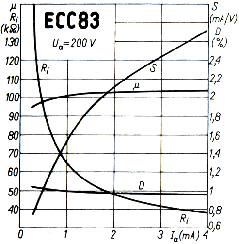
| Hi Brice, I have read your thread in the Google Groups uTracer forum, titled "Low GM test results," under the handle, "BHdeC" and can see that this issue has troubled you for some time. Sorry for your frustration but I think we can soon get to the bottom of it. Please refer to the chart seen here: http://www.tronola.com/misc/ECC83_Gm_chart.png (You might want to right-click the link and open it in a new window.) The line labeled "S" is Gm and the scale on the right is in thousands of micromhos. For example, at 1mA, it has about 1550umho. Notice that at 0.3mA, it has only about 800umho. So operating current is a critical parameter in tube testing. By changing the current, you can get vastly different results. The MaxiPreamp tester manual does not make clear what the conditions of the Gm test are but as mentioned before, they may be much higher than the 0.3mA you mentioned. The other tester mentioned in the thread was Sencore MU-150. I will say that it seems to be a cut above some others from the old days but still the supplies are for the most part, unregulated and control over operating conditions is limited. It attempts to hold operating current to a fixed value of 2, 7 or 25mA. At the lowest of those, the ECC83 chart shows Gm at about 2130umho, so that may explain the lower readings you are seeing with the uTracer. Right now, I'm plugging-in a JJ ECC83 into the uTracer and running a quick test. Using a chart of plate curves, I see that, at Va=200V, I need to set Vg= -1.1V to get about 2mA to match the Sencore. Running the quick test gives Gm=2480umhos, which exceeds the Sencore reading. On the VTA, with the same voltage settings, I get Gm=2270, so the uTracer reads about 9% higher in this case. Also for those settings, the uTracer gives 2.08mA and the VTA gives 2.09mA. In case you're wondering, the VTA shows that Vg= -1.16 gives Ia=2mA for this tube and Gm=2217 there. I think you can see that the discrepancies you are seeing can be explained by the different test currents and different tester methodologies. By the way, the heater supply issue in the uTracer is a real and known problem, not just for power tubes. It's essential to power the heater from an external supply, as shown in the article. I will be happy to help if you have further questions. Thank you for diligently pursuing this issue. Doing this kind of crossing-checking and investigation helps everyone understand their instruments and how to use them to best advantage. |
| Posted by Brice | July 06, 2019 - 10:16 pm |
| Thanks Steve. I've posted my findings to the Utracer Google group forum. Ron is aware and looking into to. But definitely, the lowest the measured current is the worse the precision is, to not relevant anymore. Cheers. |
| Posted by Steve L. | July 03, 2019 - 08:34 am |
| Hi Brice, Thank you for the kind comments. It's true that the accuracy of the µTracer may be reduced for some low-bias tubes but for the 12AX7 running at the databook condition of 0.5mA, we found that the gm reading was within 2.4% of our own VTA. The Rp reading was 3.6% off in the other direction, so mu was only about 1.2% off relative to the VTA. Regarding the MaxiPreamp tester, I notice that it seems to operate the tube in a peculiar set of conditions and it's unclear whether it is measuring true gm and mu. For example, the manual conflates the terms, gain and mu, then shows a chart which appears to list values of external Rp used in the gain test. The problem is, mu is supposed to be the voltage gain for an infinite external plate resistor. For the gm measurement, it's not clear what the conditions are and to be able to compare the reading to the µTracer, one would need to know them. Are they the same as the Gain measurement chart? If so, one can only choose 1, 2 or 4mA, so the gm measured would be very different from that seen by the µTracer, operating at the value you mentioned of 0.3mA. Too often, we speak of a tube's gm as if it's a constant, when in fact, it's strongly dependent on operating conditions. Whenever I speak of a tube's "ideal gm," it's based on the specific conditions given in standard databooks. I really appreciate your bringing up this interesting topic because it seems we are only starting to emerge from the dark days of tube testers of yore which purported to test gm but didn't operate tubes at standard conditions. |
| Posted by Brice | June 30, 2019 - 06:32 pm |
| Very nice article. Excellent source of information. I've build one on these UTracer and I am very please with it. It works great for most tubes with decent emission. However, for low current tube, typically 12ax7 with a static emission lower than 0.3mA, the gm and mu values are totally off, compared with a MaxiPreamp tester. This is a problem for me. |
| Posted by Steve L. | June 14, 2019 - 05:37 am |
| Hi Josh, Your implementation of the µTracer looks really nice! Thanks for the link and tips for using the Bluetooth and USB modules. |
| Posted by Josh | June 14, 2019 - 05:27 am |
| Hi Steve, I like your tube tester! One thing I would consider is using USB and Bluetooth instead of the serial port connector. I have my uTracer working with both. You can see my tips here: https://www.dos4ever.com/uTracer3/uTracer3_pag9.html Search for “2018 Josh” and the notes with photos of my build will pop up. You’ll see I also designed a regulated power supply so I can use it with an IEC socket. |
| Posted by Sven | June 06, 2019 - 06:01 am |
| Well, I have the M107 too but use it rarely. For tubes there is not enough current capability. As heater supply for the uTracer I use the model PL550-1 Trygon. Max current is 1 A not sufficient for big tubes. There I have other power supplies when necessary. |