
|
Moorepage
Projects, info & thoughts from Dick's lab |
|
Most recent update 1-11-2012 Modification of an old hot tub to use a digital temperature controllerFall, 2007 If you're reading this, you're probably wondering what my modifications are and why I did them. Maybe, like me, you have an older tub that doesn't hold its set temp very well or has other problems with the heater system. If so, you can fix it -- read on. I've put some narrative here to give a fuller picture of the project. Feel free to skim. Our hot-tub is a 5' by 7' "Mr. Spa" brand, built in the mid-80s, so it has (or did have) all-analog controls. It's a two-person rectangular model we got used a few years ago. The electrical parts were all showing their age -- the steel control box was corroded, the wiring was pretty heat-baked, and many connections were loose. The tub itself and all the plumbing were in great shape, and it had a new cover. The heater was working and all the pumps seemed to be OK. The principal objective was to get it working "right now." The tub was designed for 120V operation, and I could see that the total power draw, maximum, was going to require a 20A service that included GFCI protection, which is code nearly everywhere now. An electrician installed the outlet for us, to code, which cost us more than the used tub did. I made a wiring diagram (tedious) and replaced some components and a lot of wire and crimp terminals. I wasn't sure what was a "feature," what was essential, and what was not needed -- we had never owned a hot tub before. I tested the pumps -- basic smoke test, do they actually run? -- all good, and then checked the heater element and thermostats -- basic electrical tests with an ohmmeter, to check for shorts and opens -- again, all good. The relays seemed to be working. So, I filled it up and turned it on. Because this is a 120V model, it took a long time to get hot, but it did eventually. With the roughly 1500 Watts the heater delivers at 120V, raising about 250 gallons of water from roughly 55°F. to 105°F took about 18 hours. Problems Through the first summer of use, I learned some things: 1) The mercury-bulb thermostat (the bulb was in a thermowell that is part of the heater assembly) didn't hold the water at a constant temperature. Depending on various factors, the spread was 3-4°F with the cover closed, which was not so good -- normal, perhaps, but not good. 2) Keeping the water clear and clean was not easy. 3) The air button and triple-microswitch assembly for the jet pump and the air blower were all hit-or-miss. 4) Having the various pump functions controlled sequentially by the single air button was a total pain. 5) I never easily or quickly knew how hot the water was. 6) I discovered an Ozonator® hiding in a corner that was completely dead, corroded, and disconnected. Initially, I had the tub running through the timer for several cycles a day. it took a while, but I figured out that the water was much fresher and clearer if the circulation pump ran all the time, instead of just running when the heater was on or when the timer was on, so I bypassed the timer, connected the circ. pump to the 120V supply through a switch, and left it on. Then the circ. pump, a Little Giant brand small pump with its motor in an oil-filled, sealed housing, died with bearing failure. Taking it out, I discovered that the tub had to be drained to work on the circ pump or the heater assembly, so once the tub was drained and the Little Giant was out, I installed a ball valve in the supply (suction) hose from the tub bottom to the circ pump. I bought a new pump of the same type, because that's what the tub housing was designed for, and it lasted about nine months. While the Little Giant went home to be fixed under warranty, I replaced it with a larger but cheap Chinese pump designed for garden pools. The garden pump wouldn't fit the housing, so I used a SawzAll to cut the back of the fiberglass housing out and stuck the pump in the open space under the end of the tub. The garden pump was way, way too noisy, but worked OK -- except for the rust from the iron pump parts. The Little Giant came back, went in, and lasted about six months. Same song, second verse: The Little Giant came back and went in, and lasted about six months. Gave up on Little Giant and got a Waterway Tiny Might, which is still going strong. None of these small pumps appear to have very good reliability. Along the way, I decided to try a new ozone generator in order to reap the claimed benefits of better water quality with less chemical treatment, and got one from a well-regarded company. It quit after about nine months. The company was very helpful and replaced the bad ballast and sent it back. It lasted about six months. Same song, second verse: It came back and lasted about six months, and I gave up on it. Their QC department was mystified about what was blowing their ballasts. I did a lot of power-line testing for glitches and spikes, and saw absolutely nothing, and none of our many other fluorescent fixtures have had any problems. I guess they just had a bad batch of ballasts. But I didn't really think it was all that useful anyway, and I didn't like the ozone floating around -- it seemed to accelerate all sorts of problems including strange growths and lots of corrosion effects. Then the heater assembly's thermostat went completely wacky, so I got a new heater assembly complete with thermostat and high-limit thermostat, and put it in. I expected the temperature control to be tighter. It wasn't. Then the heater element assembly developed a water leak around one of the thermowells (this, BTW, is an on-going problem for me -- I'm now replacing my third heater element, all due to leaks). It was by now out of warranty, so I got another new one. That was when I decided to take a fresh look at the whole control apparatus. It's clear to me that many tubs are just plain given-up on by owners who can't fix them themselves and get tired of paying for constant repairs. Solutions From the beginning, I had envied having a new controller system with digital controls and a temperature readout, which would replace all the bits that were flaky in my system. But the issue of cost kept getting in my way, and I also thought I could build one as good as any I could buy. So, I kept fixing little bits and pieces while I thought about how best to build a control system from scratch. I thought a lot about using a microcontroller like a PIC or BasicStamp, with a touchpad control panel and an LED teadout, but the tedium of designing, assembling, and programming, as well as uncertainties about control loop configurations, kept me from starting, and besides the tub was working, sorta. First among the things I wanted was tighter temperature control and I wanted a digital thermometer built-in. I also wanted to re-organize the air button/switch situation, and I wanted to get rid of the timer, which I don't use. I also wanted to find a better, quieter solution for controlling the heater than the moderately noisy relays. Many tubs use large, high-current contactors of the kind used for motor controls, and boy do they make a lot of noise. I Googled a bunch of links for control systems and discovered that commercial spa control system "packs" now all have a 104°F. top temp, which just is not hot enough for us. That was the final nail in the coffin of "just buy one." Important -- we do not stay in the tub for long periods of time, generally less than 10 minutes per session, so we can use a higher than 104° water temperature. If you tend to use the tub for longer periods or often have small children in the tub, Do not exceed 104° settings. It's like giving yourself a very high fever and it can be dangerous. Eventually, I found on eBay a 1/16 DIN-size temperature control unit designed for industrial heater systems of all kinds, like kilns and furnaces. The VTC-620 PID controller offers proportional, integral, and differential control modes (hence "PID") via a built-in computer with self-training and fuzzy logic capabilities. It contains 2 relays, a DC output to drive a solid state relay (SSR), a digital temp display, a digital setting display, and it can use just about any type of temp sensor you can think of. It was inexpensive, from China. I also found a 75A, 240+V rated SSR to do heater control, which was also inexpensive on eBay. I ordered those parts, plus a heat sink for the SSR. Then research revealed that a Pt100 RTD platinum temp sensor was the best kind for tight control, since my controller provides 0.1°F. resolution with that sensor type. So I found one of those on eBay, too. ("Pt 100" means the platinum resistance sensor element has a value of 100 ohms at 0°C. "RTD" seems to mean Resistance Temperature Detector.) I built a new housing using a standard 8" square x 4" deep plastic electrical box, and eliminated all of the original plugs and sockets for the motors and heater, except a standard 120V 3-prong outlet for the circ. pump. I was pretty sure I might want to easily unplug it some time without going into the control box. I used a ten-point high-current barrier strip to make the various connections. I mounted the SSR in the side of the control box on a heat sink by making a slot in the side of the box that goes between fins on the heat sink, which made mounting secure and simple. I put the new box where the old one had been, and the fit was perfect. I added a new air button and air switch assembly for the jet pump, and replaced the air button and switch assembly for the air blower, too. I installed the temp controller in the face of the box, and cut an opening in the access door on the tub so I can see the displays. 
Control box interior, showing barrier strip with connections. The SSR with heat sink is top left. The air switch assemblies also are on the left. A maintenance switch that disables the heater and circ pump is on the right. 
Controller in the box. Note that the actual temp, red digits, is the same as the set temp, green digits. The hoses from the air buttons to the air switches are on the left, under the heat sink. The electrical connections for the jet pump, air blower, and the heater are on the right side. The heater assembly is beneath the box. The main electrical input line is on the bottom side, as is the cord and plug for the circ pump.
It took some fooling around to mount the RTD sensor probe (6mm diameter, 150mm long) in the water stream, but note that only the very tip of the probe is the temp sensing point -- say about the end 10mm. I used PVC and brass fittings, and a compression fitting adapter with a 1/4" silicone rubber cone washer to get a good seal around the smooth shaft of the sensor probe.
I put the temp sensor upstream from the heater assembly and downstream from the circ. pump, which was physically handy, and a good spot thermally. I didn't have to worry about sensor insulation or dead-water issues, since the water is always flowing over the sensor because the circ. pump is always on. 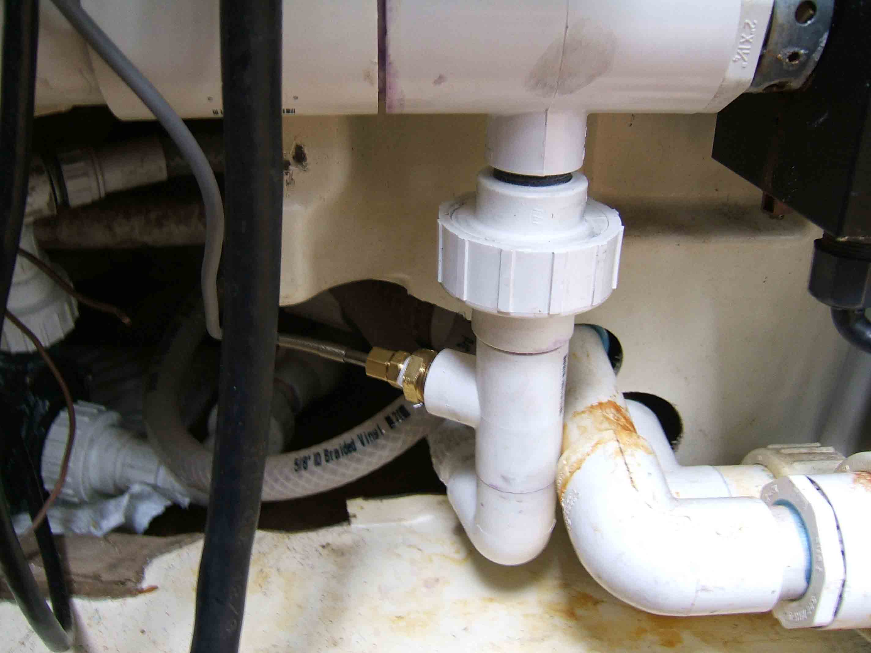
RTD temp sensor and its plumbing. The circ pump is peeking through on the left. Water flows from the circ pump up past the sensor into the heater assembly, then left and up to the filter and then back to the tub. I connected everything, and set the heater assembly thermostat to full-on, which I knew from past experience resulted in a temperature of about 110°F, so that the new controller could take over. Everything passed the smoke test. I quickly discovered that the system holds temperature to within 0.2°F. when the cover is closed. The maximum drop when we use the tub is about 0.7°F., which is very tolerable, and we can have any temperature we want up to the high-limit trip point -- both the adjustable thermostat and the high limit thermostat built into the heater assembly provide protection against way-too-high temps or a continuous-on failure mode in the new heater control. The PID controller has NVRAM for settings, so if power burps, the system returns automatically to its set values. The system is easy to read, accurate, and so far, reliable. Power has burped and nothing untoward has happened. The SSR does its power switching on the AC zero-crossing points, so there's no electrical noise in our house due to switching transients. And the SSR can be switched with a very high duty cycle without anything wearing out, which improves system response. Programming the controller was easy enough after I figured out what the makers meant by various identifiers and control modes, all written in a terse and enigmatic English translation. There is a provision for the controller's fuzzy-logic computer to program itself, but I didn't want to wait for days for the cycle to complete, given the slow response time of the tub temp in both directions. I used default values for parameters, and then fine-tuned a bit, and all is well. Here's a PDF document you can download that details the PID Controller's features, settings, and notes on usage: PID Controller manual. Please note that there is an error in the description for using a two-wire RTD. The manual says to short terminals 6 and 7. It should say to short terminals 9 and 10. The manual's wiring diagram shows this correctly, but the description is wrong. Here's the wiring diagram of the mods in PDF format that you can download -- I think you'll be impressed with its simplicity: Hot tub wiring diagram. Temperature sensors other than an RTD can be used, such as a standard K type thermocouple (one of which came with the controller), but this controller then only offers 1 degree resolution on temp settings, and I think the standard K thermocouples are a pain to mount. The actual control may be very precise, but I wanted finer setting control to at least 1/2 degree, and the controller and a Pt100 RTD sensor give that and more. I checked calibration of the controller and sensor together before installing them, using rapidly boiling water and a crushed ice-water slurry, and they were within a couple tenths of a degree of 212 and 32 -- pretty good given the variables in testing method and controller-sensor interaction. I now use a floating chlorine dispenser with 1" tablets for continuous chlorination. We like that; many don't. But a key element of keeping water nice has been the continuous circulation, and then keeping the filter clean. This tub is now completely fabulous, and maintenance has dropped to almost nothing.... at least until this circ. pump dies.... By the way, the only noise from the tub now is a soft hum and gurgling from the circ pump. 
All done. Parts sources and cost The PID controller, the SSR and the heatsink all came from the eBay Store "tibetwalk" through their auctions, and they were very helpful. They seem to be here in the US, but the parts come from Hong Kong, and fairly quickly and inexpensively by Airmail. The RTD was a "Buy It Now" on eBay and cost me $25. All the parts for the mod came to about $140 total, including the air button and switches. June 2011 update -- I've had to replace the PID controller and two SSRs in the intervening years -- the second SSR just this month. My first PID controller and SSR just quit working in December, 2010, between Christmas and New Years, and had a "burned-resistor" smell. I bought a $35 replacement controller unit, a JLD612, and a $25 60A SSR from Lightobject.com in California, who shipped immediately. The JLD612 is essentially identical to the previous controller, with only a few differences in control functions, menus, and settings. I've amended the setting page at the end to show what the controller's AT PID auto-tuning system came up with, and what I'm using now. I had the good sense to also buy a spare SSR. So, When the tub quit heating a week ago, I finally figured out that the SSR was intermittent, even though it seemed to be working. I put in the spare and all is again well. I've also now had to replace the Waterway Tiny-Might circulation pump -- it got very noisy and sometimes wouldn't start up after I turned if off. January 2012 update -- I have again had to replace the circulation pump -- the Infinity Garden Pump's magnetic drive proved to be unbearably noisy. This time I've purchased a very nice Grundfos 120V pump designed specifically for continuous operation in hot tubs -- you can Google "spa circulation pump" for some suppliers. It has a nice mounting system and is dead quiet -- by far the quietest pump I've used. The motor is totally sealed in the housing, and the whole unit is compact. I have high hopes for this one. The Waterway Tiny Might is available again, but is larger and noisier, so the Grundfos is the top choice for now. Some issues with control In doing the schematic diagram of the original system, there were elements of the design that I didn't grok at first. It is much easier to figure out what the circuit does when you know what it is supposed to do, and I had no idea. For example, the air blower circuit had an extra normally-closed microswitch that appeared to open the heater relay coil circuit when the air blower was switched on. After a lot of thought, I realized that they didn't want to risk a lot of air getting to the heater element, which would get sucked in by the circ pump and potentially cause element burn-out. I kept that feature in the new system. The various interdependencies of the switches and relays were total bears to figure out, especially since one routing of power involved turning the circ pump on and off only with the heater, but another had the circ pump controlled by the heater and/or the timer. January 2012 update -- James Sweet emailed to observe that the hot tub makers turn off the heater in 120V models to keep the total current drawn by the tub under the usual current rating for 120V branch outlets. I actually hadn't considered this obvious point -- I have a higher current outlet that doesn't have this power restriction -- most people don't. I still don't understand the whys and wherefores of using a timer on a hot tub. Some timer systems probably turn the heater on and off, if they have a fast recovery time, so you could run the tub like you heat your house and just heat it a while before you'll use it. A 240V system will deliver 6kW of power to the heater. In my tub, that heater would only need about 5 hours to raise a cold fill to usable temp, so it would only take a short time to raise water temp by a few degrees, and that might be practical. We're retired, so you just never know when one of us is going to jump in the tub any time of day or night, so we keep it hot. What about 240V systems? If you have an older tub you'd like to convert and it's a 240V system, everything I used, you can use too. In many systems, you will need four of the 75A SSRs to provide separate control over high-limit protection and temp control. Those systems typically switch both sides of the 240V supply, with the high-limit thermostat controlling the drive to two of the SSRs, and the PID controller driving the other two. Note that you'll need a source of low-voltage DC for some of the SSR types, but there are models available that use either-or-both low-voltage or line-voltage AC for control. For those AC-drive SSRs, one side of the 240V line can be routed through the high-limit thermostat and then to those two SSRs connected in parallel. The temp control thermostat, of course, is no longer needed and should be bypassed in the heater assembly if that's where it is. I used a heat sink on the SSR just to be sure that it wasn't going to suffer from heatstroke with the 12 to 14A of heater current. With heat sinks, I think they will work fine at the double current of the 240V system -- twice the voltage, twice the current, and four times the heater power for 240V vs. 120V. Having a lot of extra current capacity in the SSRs is vital, because they are only good at their rated current when their cases are at a normal ambient. But these things get hot and need both the extra rating and the heat sinks to be reliable. June, 2008 Update -- The brass fittings holding the RTD sensor into the plastic Tee did not hold up -- I thought that their relative thickness would let them last for a few years, but no dice -- small pinholes appeared and the water level in the tub began to drop. Since the RTD sensor I use has a 6mm diameter casing (Just under 1/4"), I got a short piece of 1/4" ID vinyl tubing and a 1/2" pipe-thread PVC cap. I bored a hole in the end of the cap to fit the tubing's OD (approx. 3/8"), then glued the tubing into the hole with PVC cement. I screwed the cap onto the end of the Tee, put some Aladdin Teflon Magic Lube® on the RTD sensor casing, and stuffed it into the vinyl tube. I then used some aluminum wire twisted around the outside of the vinyl tubing to make a watertight seal. A couple of small plastic tie-wraps would probably work better, but it's working just fine for now. A note about water chemistry Keeping the water slightly alkaline, with a pH of 7.2 to 7.6 is crucial. I'm sure the heater leaks and other leak problems I've had have been due to the water being slightly acidic, with pH sometimes in the 6.8 area or lower. It's not clear to me how the water goes from higher to lower pH -- it may be due to something in the chemistry of the chlorine tablets I use for purification. Our water supply is neutral at 7.0, so something is moving it down. I'm trying one of the copper-ion solutions, Rain Forest Blue®, for purification. But by itself, it is not enough, so I'm using the chlorine tablets as well, but at a lower concentration. Together, they seem to work fine, with less chlorine odor on our bodies after getting out. January 2012 update -- Turns out that Robert's Hot Tubs website has the explanation for the increasing acidity -- it is due to the chlorine tablet chemistry, which lowers the pH as the tablets dissolve and the chlorine level rises. This process accelerates quite quickly, so using a pH increaser (like soda ash or the widely available powders) once a week or so is vital to keeping the pH in the acceptable range. March, 2010 Update -- Nothing is perfect or at least not forever. I discovered in late December that the tub was not heating -- the temperature was dropping, and yet the controller showed that it was turning the heater on. This could only mean that either 1) the controller was faulty, 2) the heater was faulty, or 3) that the solid state relay (SSR) was faulty. Opening the controller box revealed a burned component smell and a burned section of the SSR. I powered the system off and checked the heater element for resistance and it was OK, so only the SSR was bad. I didn't have a spare, so the tub was down for five days while a new SSR came from an eBay seller in California, who kindly shipped the new one on Christmas Eve. Once the new SSR was in, all was well again. I now keep a spare SSR and controller on hand. My Settings Summary -- no value means no change I did not originally use auto-tuning to set PID parameters My orig. AT My new Initialization Loop (Inty)=Pt10.0 (outy)=2 (SSR) (Atdu)=10 this is now (Hy)=0.3 (SouF)=0.1 0.2 0.2 moved to PID Loop (rd)=0 (CorF)=1 (F) Temp Set & Alarm Loop (SV)=106.0°F (AH1)=108.0°F (AL1)=108.0°F (note: AL1=AH1 disables relay 1 and turns off AL1 LED) (AH2)=104.0°F (AL2)=104.0°F (note: AL2=AH2 disables relay 2 and turns off AL2 LED) PID Loop (P)=1.0 0.7 5.0 (I)=20 1999 200 (d)=40 399 100 (PSb)=0 moved to Initialization Loop; no change (ot)=2 (Filt)=1 0 1 I hope all this helps you if your hot tub problems are anything like mine were. January 11, 2012 update -- About SSRs  My wife woke up at 3:30AM after hearing the hot tub's air blower come on. She went downstairs to find the hot tub on fire. It was 24° F out, but fortunately clear and dry. I got a hose hooked up, lifted the tub access door, and sprayed the insides everywhere the sprayer wand would reach. As I sat there waiting to be sure the fire was out, I thought hard about the trip to Palm Springs we will begin on Friday -- it's Wednesday morning now. How did this happen? The next picture, which I've annotated, spells it out. The SSR did not short out and it did not open. It failed by burning. It then set the plastic electrical box on fire, and that in turn set the wooden tub shell on fire at the top above the door. The fiberglass tub itself has some smoke damage but is otherwise intact. 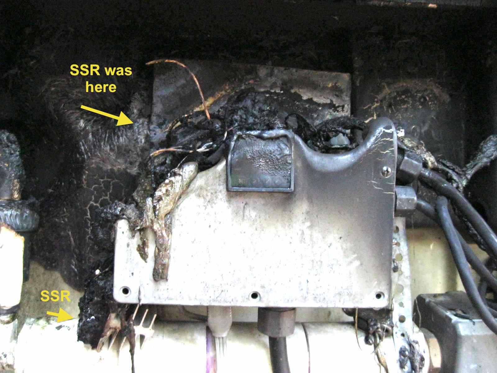 This is not the first SSR I've had fail, so I suppose I should have expected a failure. Knowing this, there are some things I would do differently: 1) House the SSR separately from the control box, in a metal enclosure spaced away from combustible materials. This would have kept the burning epoxy case of the SSR from setting fire to anything else. It would still get hot, but the near air-tight metal housing would retard the flames and prevent burning material from contacting anything else that could burn. 2) Mount the controller and the other electrical components in a metal box, too. This would serve the same good purpose for the controller and various switches as for the SSR. This was scary -- what if we hadn't been home? What if the air blower, which is very loud, hadn't come on? What if Robin hadn't awakened? Life is full of what-ifs, which is why there are various codes for construction and use. Electrical fires are common, so it makes sense, especially NOW, to makes things as fire-proof as possible. I didn't, and I was lucky... |
|
|